Arduino - LCD + I2C LCD + Hangul
https://www.circuitbasics.com/arduino-thermistor-temperature-sensor-tutorial/
MAKE AN ARDUINO TEMPERATURE SENSOR (THERMISTOR TUTORIAL)
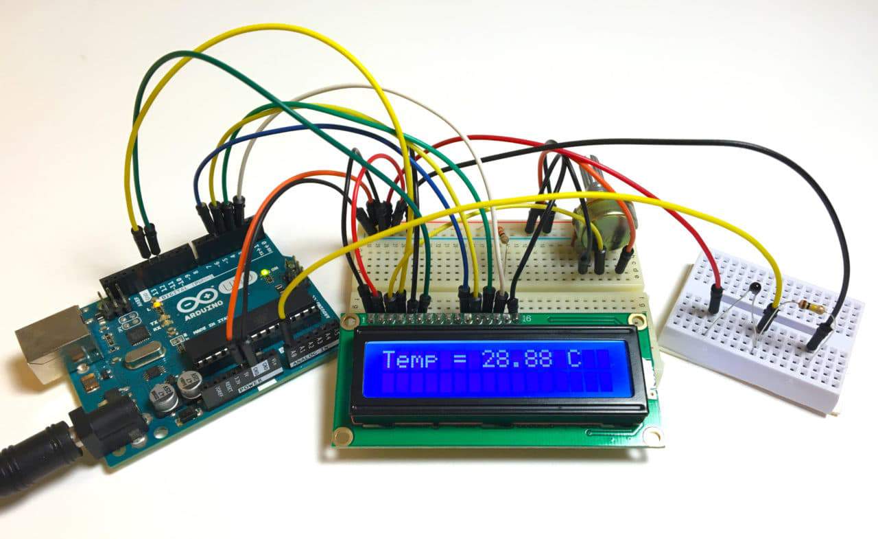
Thermistors are simple, inexpensive, and accurate components that make it easy to get temperature data for your projects. Remote weather stations, home automation systems, and equipment control and protection circuits are some applications where thermistors would be ideal. They’re analog sensors, so the code is relatively simple compared to digital temperature sensors that require special libraries and lots of code.
In this article, I’ll explain how thermistors work, then I’ll show you how to set up a basic thermistor circuit with an Arduino that will output temperature readings to the serial monitor or to an LCD.
HOW A THERMISTOR WORKS
Thermistors are variable resistors that change their resistance with temperature. They are classified by the way their resistance responds to temperature changes. In Negative Temperature Coefficient (NTC) thermistors, resistance decreases with an increase in temperature. In Positive Temperature Coefficient (PTC) thermistors, resistance increases with an increase in temperature.
NTC thermistors are the most common, and that’s the type we’ll be using in this tutorial. NTC thermistors are made from a semiconducting material (such as a metal oxide or ceramic) that’s been heated and compressed to form a temperature sensitive conducting material.
The conducting material contains charge carriers that allow current to flow through it. High temperatures cause the semiconducting material to release more charge carriers. In NTC thermistors made from ferric oxide, electrons are the charge carriers. In nickel oxide NTC thermistors, the charge carriers are electron holes.
A BASIC THERMISTOR CIRCUIT
Let’s build a basic thermistor circuit to see how it works, so you can apply it to other projects later.
Since the thermistor is a variable resistor, we’ll need to measure the resistance before we can calculate the temperature. However, the Arduino can’t measure resistance directly, it can only measure voltage.
The Arduino will measure the voltage at a point between the thermistor and a known resistor. This is known as a voltage divider. The equation for a voltage divider is:

In terms of the voltage divider in a thermistor circuit, the variables in the equation above are:

This equation can be rearranged and simplified to solve for R2, the resistance of the thermistor:

Finally, the Steinhart-Hart equation is used to convert the resistance of the thermistor to a temperature reading.
CONNECT THE CIRCUIT
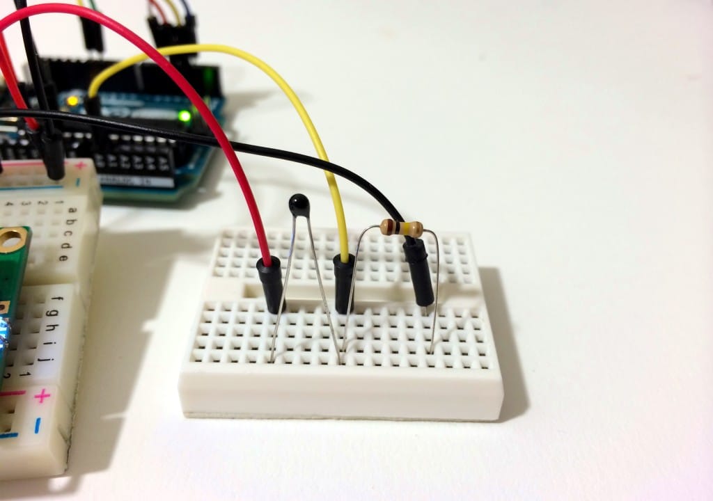
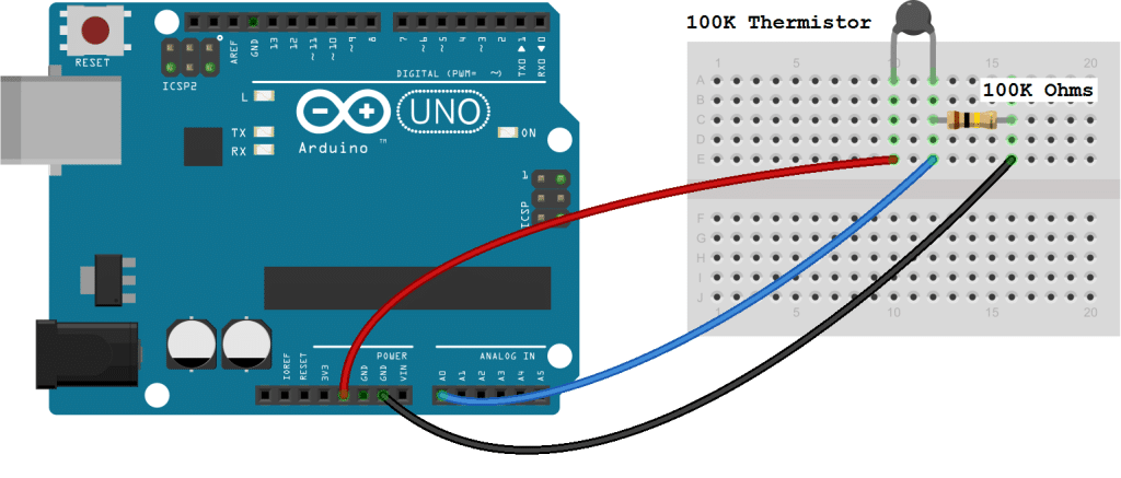
Connect the thermistor and resistor to your Arduino like this:
The value of the resistor should be roughly equal to the resistance of your thermistor. In this case, the resistance of my thermistor is 100K Ohms, so my resistor is also 100K Ohms.
The manufacturer of the thermistor might tell you it’s resistance, but if not, you can use a multimeter to find out. If you don’t have a multimeter, you can make an Ohm meter with your Arduino by following our Arduino Ohm Meter tutorial. You only need to know the magnitude of your thermistor. For example, if your thermistor resistance is 34,000 Ohms, it is a 10K thermistor. If it’s 340,000 Ohms, it’s a 100K thermsitor.
CODE FOR SERIAL MONITOR OUTPUT OF TEMPERATURE READINGS
After connecting the circuit above, upload this code to your Arduino to output the temperature readings to the serial monitor in Fahrenheit:
int ThermistorPin = 0;
int Vo;
float R1 = 10000;
float logR2, R2, T;
float c1 = 1.009249522e-03, c2 = 2.378405444e-04, c3 = 2.019202697e-07;

void setup() {
Serial.begin(9600);
}

void loop() {

  Vo = analogRead(ThermistorPin);
  R2 = R1 * (1023.0 / (float)Vo - 1.0);
  logR2 = log(R2);
  T = (1.0 / (c1 + c2*logR2 + c3*logR2*logR2*logR2));
  T = T - 273.15;
  T = (T * 9.0)/ 5.0 + 32.0;

  Serial.print("Temperature: ");
  Serial.print(T);
  Serial.println(" F");

  delay(500);
}
To display the temperature in degrees Celsius, just comment out line 18 by inserting two forward slashes (“//”) at the beginning of the line.
This program will display Celsius and Fahrenheit at the same time:
int ThermistorPin = 0;
int Vo;
float R1 = 10000;
float logR2, R2, T, Tc, Tf;
float c1 = 1.009249522e-03, c2 = 2.378405444e-04, c3 = 2.019202697e-07;

void setup() {
Serial.begin(9600);
}

void loop() {

  Vo = analogRead(ThermistorPin);
  R2 = R1 * (1023.0 / (float)Vo - 1.0);
  logR2 = log(R2);
  T = (1.0 / (c1 + c2*logR2 + c3*logR2*logR2*logR2));
  Tc = T - 273.15;
  Tf = (Tc * 9.0)/ 5.0 + 32.0;

  Serial.print("Temperature: ");
  Serial.print(Tf);
  Serial.print(" F; ");
  Serial.print(Tc);
  Serial.println(" C");

  delay(500);
}
CODE FOR LCD OUTPUT OF TEMPERATURE READINGS
To output the temperature readings to a 16X2 LCD, follow our tutorial, How to Set Up an LCD Display on an Arduino, then upload this code to the board:
#include <LiquidCrystal.h>

int ThermistorPin = 0;
int Vo;
float R1 = 10000;
float logR2, R2, T;
float c1 = 1.009249522e-03, c2 = 2.378405444e-04, c3 = 2.019202697e-07;

LiquidCrystal lcd(12, 11, 5, 4, 3, 2);

void setup() {
Serial.begin(9600);
}

void loop() {

  Vo = analogRead(ThermistorPin);
  R2 = R1 * (1023.0 / (float)Vo - 1.0);
  logR2 = log(R2);
  T = (1.0 / (c1 + c2*logR2 + c3*logR2*logR2*logR2));
  T = T - 273.15;
  T = (T * 9.0)/ 5.0 + 32.0;

  lcd.print("Temp = ");
  lcd.print(T);
  lcd.print(" F");

  delay(500);
  lcd.clear();
}
Here’s a video of the temperature sensor so you can watch me set it up and see how it works:
Well, that’s about it. Just leave a comment below if you have any questions about this project. And if you like our articles here at Circuit Basics, subscribe and we’ll let you know when we publish new articles. Also, feel free to share this if you know anyone that would find it helpful!
Sign Up & Get at Least Two $5 Coupons Now: https://jlcpcb.com/quote
ARDUINO LCD SET UP AND PROGRAMMING GUIDE
In this tutorial, I’ll explain how to set up an LCD on an Arduino and show you all the different ways you can program it. I’ll show you how to print text, scroll text, make custom characters, blink text, and position text. They’re great for any project that outputs data, and they can make your project a lot more interesting and interactive.
The display I’m using is a 16×2 LCD display that I bought for about $5. You may be wondering why it’s called a 16×2 LCD. The part 16×2 means that the LCD has 2 lines, and can display 16 characters per line. Therefore, a 16×2 LCD screen can display up to 32 characters at once. It is possible to display more than 32 characters with scrolling though.
The code in this article is written for LCD’s that use the standard Hitachi HD44780 driver. If your LCD has 16 pins, then it probably has the Hitachi HD44780 driver. These displays can be wired in either 4 bit mode or 8 bit mode. Wiring the LCD in 4 bit mode is usually preferred since it uses four less wires than 8 bit mode. In practice, there isn’t a noticeable difference in performance between the two modes. In this tutorial, I’ll connect the LCD in 4 bit mode.
CONNECTING THE LCD TO THE ARDUINO
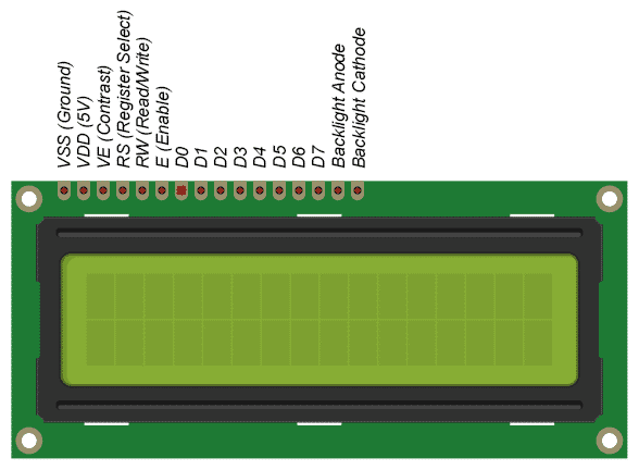
Here’s a diagram of the pins on the LCD I’m using. The connections from each pin to the Arduino will be the same, but your pins might be arranged differently on the LCD. Be sure to check the datasheet or look for labels on your particular LCD:
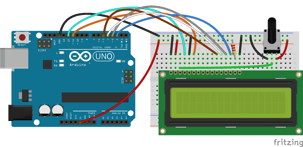
Also, you might need to solder a 16 pin header to your LCD before connecting it to a breadboard. Follow the diagram below to wire the LCD to your Arduino:
The resistor in the diagram above sets the backlight brightness. A typical value is 220 Ohms, but other values will work too. Smaller resistors will make the backlight brighter.
The potentiometer is used to adjust the screen contrast. I typically use a 10K Ohm potentiometer, but other values will also work.
Here’s the datasheet for the 16×2 LCD with all of the technical information about the display:
PROGRAMMING THE ARDUINO
All of the code below uses the LiquidCrystal library that comes pre-installed with the Arduino IDE. A library is a set of functions that can be easily added to a program in an abbreviated format.
In order to use a library, it needs be included in the program. Line 1 in the code below does this with the command #include <LiquidCrystal.h>. When you include a library in a program, all of the code in the library gets uploaded to the Arduino along with the code for your program.
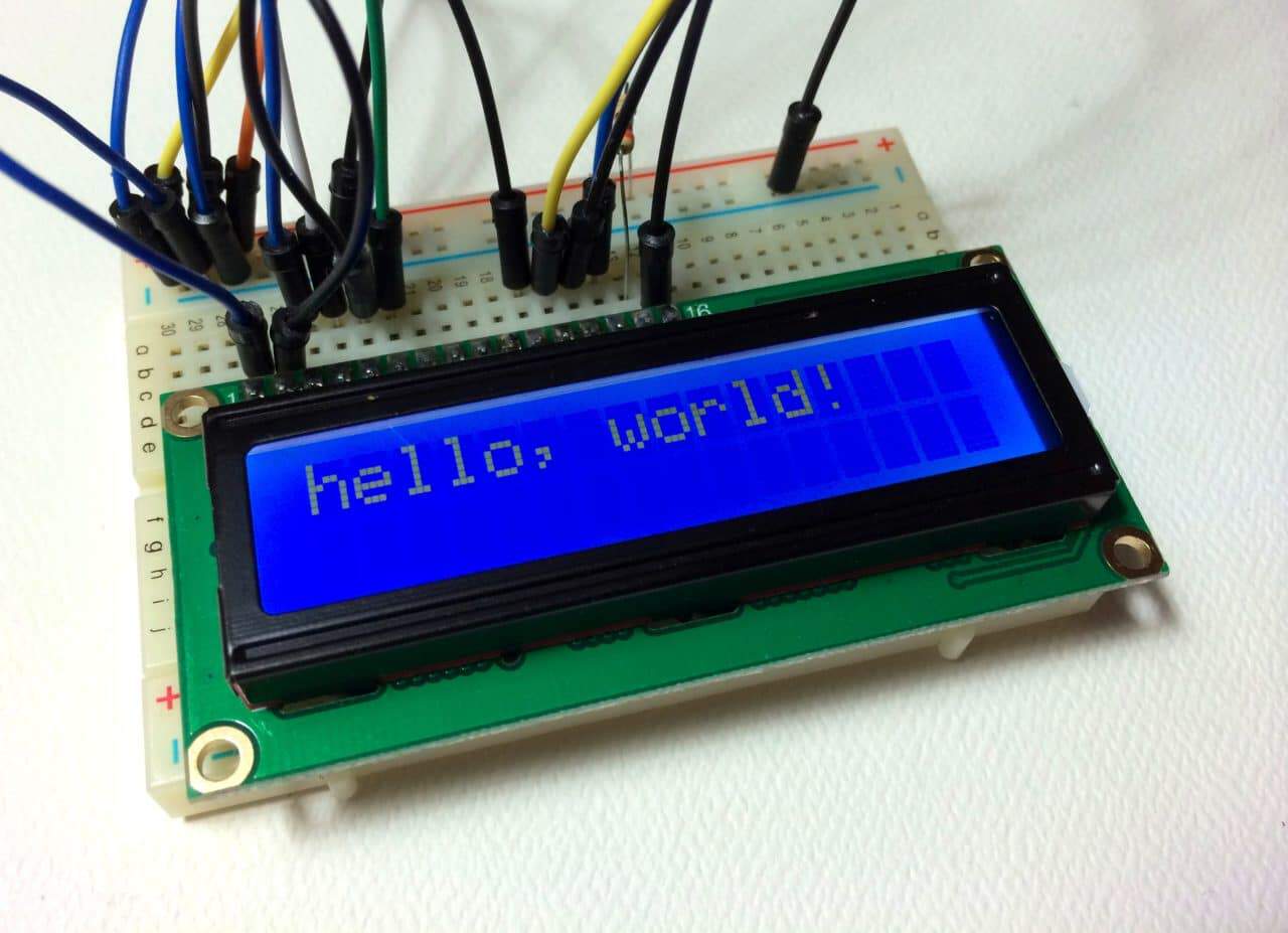
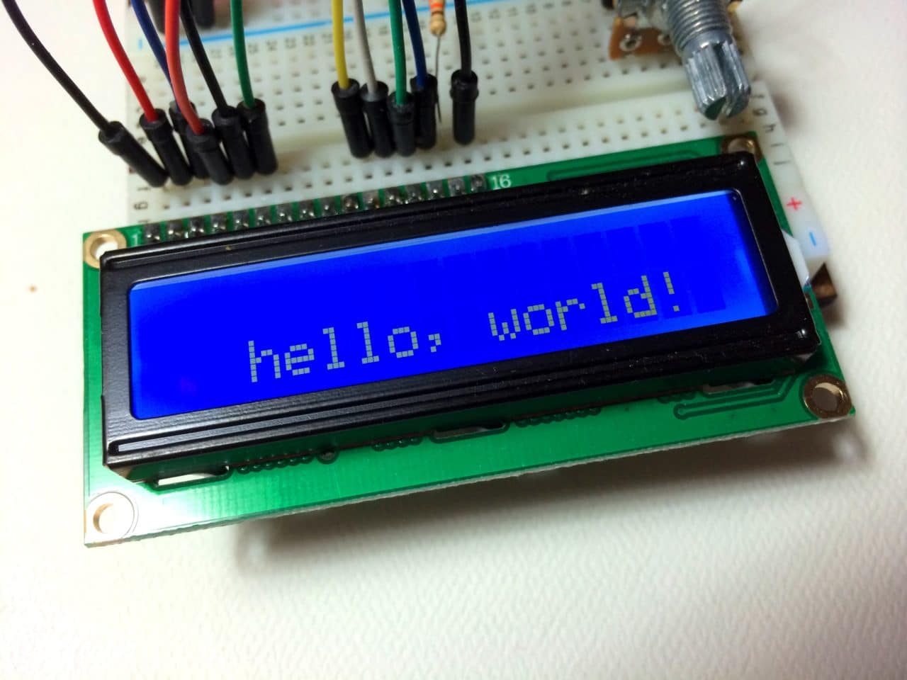
Now we’re ready to get into the programming! I’ll go over more interesting things you can do in a moment, but for now lets just run a simple test program. This program will print “hello, world!” to the screen. Enter this code into the Arduino IDE and upload it to the board:
#include <LiquidCrystal.h>

LiquidCrystal lcd(12, 11, 5, 4, 3, 2);

void setup() {
  lcd.begin(16, 2);
  lcd.print("hello, world!");
}

void loop() {
}
Your LCD screen should look like this:
LCD DISPLAY OPTIONS
There are 19 different functions in the LiquidCrystal library available for us to use. These functions do things like change the position of the text, move text across the screen, or make the display turn on or off. What follows is a short description of each function, and how to use it in a program.
LiquidCrystal()
The LiquidCrystal() function sets the pins the Arduino uses to connect to the LCD. You can use any of the Arduino’s digital pins to control the LCD. Just put the Arduino pin numbers inside the parentheses in this order:
LiquidCrystal(RS, E, D4, D5, D6, D7)
RS, E, D4, D5, D6, D7 are the LCD pins.
For example, say you want LCD pin D7 to connect to Arduino pin 12. Just put “12” in place of D7 in the function like this:
LiquidCrystal(RS, E, D4, D5, D6, 12)
This function needs to be placed before the void setup() section of the program.
lcd.begin()
This function sets the dimensions of the LCD. It needs to be placed before any other LiquidCrystal function in the void setup() section of the program. The number of rows and columns are specified as lcd.begin(columns, rows). For a 16×2 LCD, you would use lcd.begin(16, 2), and for a 20×4 LCD you would use lcd.begin(20, 4).
lcd.clear()
This function clears any text or data already displayed on the LCD. If you use lcd.clear() with lcd.print() and the delay() function in the void loop() section, you can make a simple blinking text program:
#include <LiquidCrystal.h>

LiquidCrystal lcd(12, 11, 5, 4, 3, 2);

void setup() {
  lcd.begin(16, 2);
}

void loop() {
  lcd.print("hello, world!");
  delay(500);
  lcd.clear();
  delay(500);
}
lcd.home()
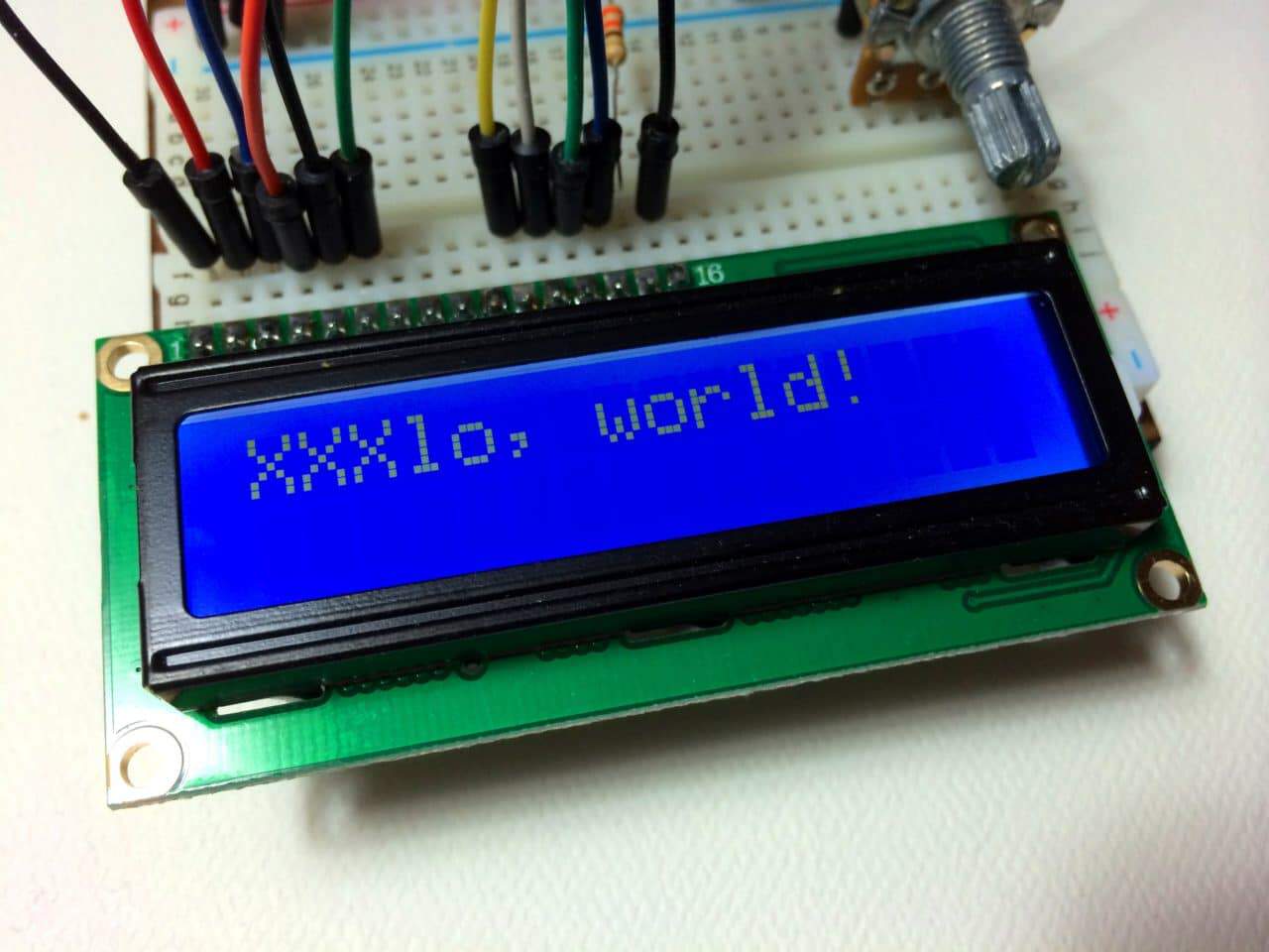
This function places the cursor in the upper left hand corner of the screen, and prints any subsequent text from that position. For example, this code replaces the first three letters of “hello world!” with X’s:
#include <LiquidCrystal.h>

LiquidCrystal lcd(12, 11, 5, 4, 3, 2);

void setup() {
  lcd.begin(16, 2);
  lcd.print("hello, world!");
}

void loop() {
  lcd.home();
  lcd.print("XXX");
}
lcd.setCursor()
Similar, but more useful than lcd.home() is lcd.setCursor(). This function places the cursor (and any printed text) at any position on the screen. It can be used in the void setup() or void loop() section of your program.
The cursor position is defined with lcd.setCursor(column, row). The column and row coordinates start from zero (0-15 and 0-1 respectively). For example, using lcd.setCursor(2, 1) in the void setup() section of the “hello, world!” program above prints “hello, world!” to the lower line and shifts it to the right two spaces:
#include <LiquidCrystal.h>

LiquidCrystal lcd(12, 11, 5, 4, 3, 2);

void setup() {
  lcd.begin(16, 2);
  lcd.setCursor(2, 1);
  lcd.print("hello, world!");
}

void loop() {
}
lcd.write()
You can use this function to write different types of data to the LCD, for example the reading from a temperature sensor, or the coordinates from a GPS module. You can also use it to print custom characters that you create yourself (more on this below). Use lcd.write() in the void setup() or void loop() section of your program.
lcd.print()
This function is used to print text to the LCD. It can be used in the void setup() section or the void loop() section of the program.
To print letters and words, place quotation marks (” “) around the text. For example, to print hello, world!, use lcd.print("hello, world!").
To print numbers, no quotation marks are necessary. For example, to print 123456789, use lcd.print(123456789).
lcd.print() can print numbers in decimal, binary, hexadecimal, and octal bases. For example:
lcd.print(100, DEC)prints “100”;lcd.print(100, BIN)prints “1100100”lcd.print(100, HEX)prints “64”lcd.print(100, OCT)prints “144”
lcd.cursor()
This function creates a visible cursor. The cursor is a horizontal line placed below the next character to be printed to the LCD.
The function lcd.noCursor() turns the cursor off. lcd.cursor() and lcd.noCursor() can be used together in the void loop() section to make a blinking cursor similar to what you see in many text input fields:
#include <LiquidCrystal.h>

LiquidCrystal lcd(12, 11, 5, 4, 3, 2);

void setup() {
  lcd.begin(16, 2);
  lcd.print("hello, world!");
}

void loop() {
  lcd.cursor();
  delay(500);
  lcd.noCursor();
  delay(500);
}
This places a blinking cursor after the exclamation point in “hello, world!”
Cursors can be placed anywhere on the screen with the lcd.setCursor() function. This code places a blinking cursor directly below the exclamation point in “hello, world!”:
#include <LiquidCrystal.h>

LiquidCrystal lcd(12, 11, 5, 4, 3, 2);

void setup() {
  lcd.begin(16, 2);
  lcd.print("hello, world!");
}

void loop() {
  lcd.setCursor(12, 1);
  lcd.cursor();
  delay(500);
  lcd.setCursor(12, 1);
  lcd.noCursor();
  delay(500);
}
lcd.blink()
This function creates a block style cursor that blinks on and off at approximately 500 milliseconds per cycle. Use it in the void loop() section. The function lcd.noBlink() disables the blinking block cursor.
lcd.display()
This function turns on any text or cursors that have been printed to the LCD screen. The function lcd.noDisplay() turns off any text or cursors printed to the LCD, without clearing it from the LCD’s memory.
These two functions can be used together in the void loop() section to create a blinking text effect. This code will make the “hello, world!” text blink on and off:
#include <LiquidCrystal.h>

LiquidCrystal lcd(12, 11, 5, 4, 3, 2);

void setup() {
  lcd.begin(16, 2);
  lcd.print("hello, world!");
}

void loop() {
  lcd.display();
  delay(500);
  lcd.noDisplay();
  delay(500);
}
lcd.scrollDisplayLeft()
This function takes anything printed to the LCD and moves it to the left. It should be used in the void loop() section with a delay command following it. The function will move the text 40 spaces to the left before it loops back to the first character. This code moves the “hello, world!” text to the left, at a rate of one second per character:
#include <LiquidCrystal.h>

LiquidCrystal lcd(12, 11, 5, 4, 3, 2);

void setup() {
  lcd.begin(16, 2);
  lcd.print("hello, world!");
}

void loop() {
  lcd.scrollDisplayLeft();
  delay(1000);
}
Text strings longer than 40 spaces will be printed to line 1 after the 40th position, while the start of the string will continue printing to line 0.
lcd.scrollDisplayRight()
This function behaves like lcd.scrollDisplayLeft(), but moves the text to the right.
lcd.autoscroll()
This function takes a string of text and scrolls it from right to left in increments of the character count of the string. For example, if you have a string of text that is 3 characters long, it will shift the text 3 spaces to the left with each step:
#include <LiquidCrystal.h>

LiquidCrystal lcd(12, 11, 5, 4, 3, 2);

void setup() {
  lcd.begin(16, 2);
}

void loop() {
  lcd.setCursor(0, 0);
  lcd.autoscroll();
  lcd.print("ABC");
  delay(500);
}
Like the lcd.scrollDisplay() functions, the text can be up to 40 characters in length before repeating. At first glance, this function seems less useful than the lcd.scrollDisplay() functions, but it can be very useful for creating animations with custom characters.
lcd.noAutoscroll()
lcd.noAutoscroll() turns the lcd.autoscroll() function off. Use this function before or after lcd.autoscroll() in the void loop() section to create sequences of scrolling text or animations.
lcd.rightToLeft()
This function sets the direction that text is printed to the screen. The default mode is from left to right using the command lcd.leftToRight(), but you may find some cases where it’s useful to output text in the reverse direction:
#include <LiquidCrystal.h>

LiquidCrystal lcd(12, 11, 5, 4, 3, 2);

void setup() {
  lcd.begin(16, 2);
  lcd.setCursor(12, 0);
  lcd.rightToLeft();
  lcd.print("hello, world!");
}

void loop() {
}
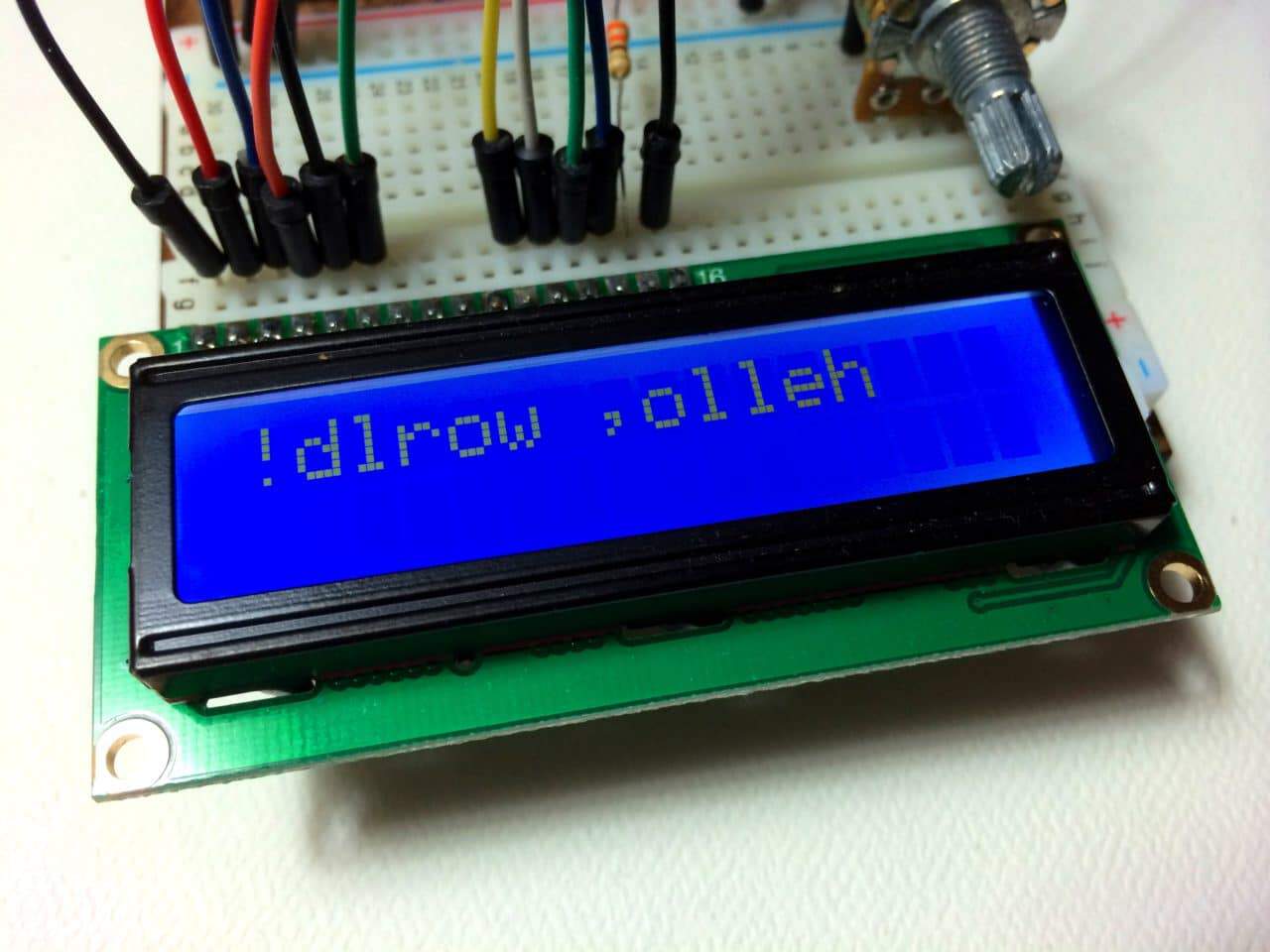
This code prints the “hello, world!” text as “!dlrow ,olleh”. Unless you specify the placement of the cursor with lcd.setCursor(), the text will print from the (0, 1) position and only the first character of the string will be visible.
lcd.createChar()
This command allows you to create your own custom characters. Each character of a 16×2 LCD has a 5 pixel width and an 8 pixel height. Up to 8 different custom characters can be defined in a single program. To design your own characters, you’ll need to make a binary matrix of your custom character from an LCD character generator or map it yourself. This code creates a degree symbol (°):
#include <LiquidCrystal.h>

LiquidCrystal lcd(12, 11, 5, 4, 3, 2);
byte customChar[8] = {
	0b00110,
	0b01001,
	0b01001,
	0b00110,
	0b00000,
	0b00000,
	0b00000,
	0b00000
};

void setup() {
  lcd.createChar(0, customChar);
  lcd.begin(16, 2);
  lcd.write((uint8_t)0);
}

void loop() {
}
There are a lot of cool things you can make happen with these 16×2 LCDs! Try combining some of these functions and see what happens.
Here’s a video version of this tutorial so you can see what each function does on the LCD in real time:
https://kocoafab.cc/tutorial/view/80
LCD-연결, 글자 출력하기
2014-08-07 10:52:37
개요
LCD는 종류, 사이즈가 다양합니다. 연결해야 할 선은 많지만 간단하게
온도, CPU 사용상태, 그림까지 출력 할 수 있기 때문에 활용도가 좋습니다.
연결해서 나만의 게임기, 알람시계등을 만들어 보세요.
출처 : forum.arduino.cc / arduinofun.blogspot.com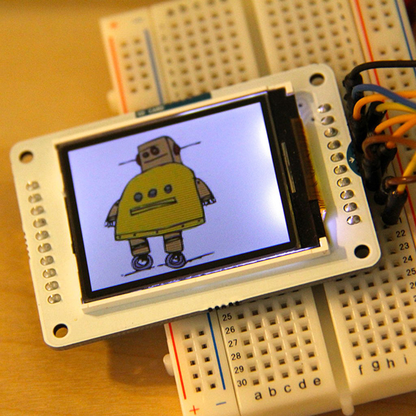
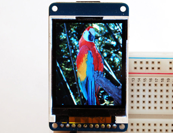
출처 : www.electronics-lab.com / www.adafruit.com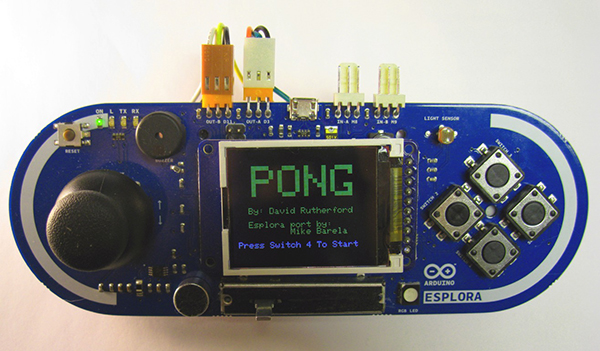
출처 : 21stdigitalhome.blogspot.com
이제 LCD를 연결하는 방법을 알아봅시다. 연결 선이 많이 있기 때문에 주의하면서 연결하세요.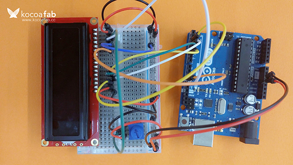
미리보기 동영상
부품목록
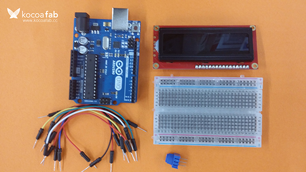
| NO | 부품명 | 수량 | 상세설명 |
1 | 아두이노 우노 R3 | 1 | |
2 | 브레드보드 | 1 | |
3 | LCD | 1 | LCD-00709을 사용했습니다. 다른 LCD를 사용할 경우 연결방법이 다를 수 있습니다. |
4 | Potentiometer | 1 | |
5 | 점퍼케이블 | 16 |
| 부품명 | 아두이노 우노 R3 | 브레드보드 | LCD | Potentiometer | 점퍼케이블 |
| 파트 | 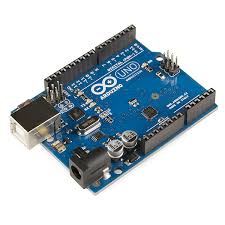 x1 x1 | 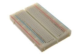 x1 x1 | 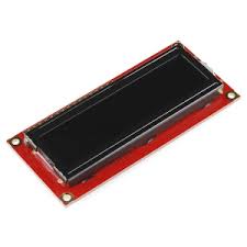 x1 x1 | 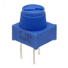 x1 x1 |  x16 x16 |
하드웨어 Making
회로도
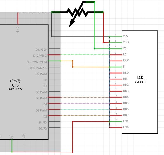
브레드보드 레이아웃
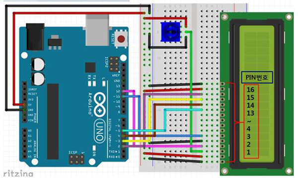
센서 연결
| LCD 핀번호 | 연결 |
| 1 | GND |
| 2 | 5V |
| 3 | Potentiometer의 가운데 핀 |
| 4 | 아두이노 12번 핀 |
| 5 | GND |
| 6 | 아두이노 11번 핀 |
| 7 | 연결안함 |
| 8 | 연결안함 |
| 9 | 연결안함 |
| 10 | 연결안함 |
| 11 | 아두이노 5번 핀 |
| 12 | 아두이노 4번 핀 |
| 13 | 아두이노 3번 핀 |
| 14 | 아두이노 2번 핀 |
| 15 | 5V |
| 16 | GND |
소프트웨어 Coding
/*
 LCD 연결해서 글자 출력하기

 이 스케치는 KocoaFab에서 만들었습니다.
 이 스케치는 누구든 무료로 사용할 수 있습니다.
*/

#include <LiquidCrystal.h>

LiquidCrystal lcd(12,11,5,4,3,2);        //RS 핀, E핀, 데이터 핀 4개
String lcdString = "";                   //객체 선언 : 출력 할 글자 저장

void setup() {
  lcd.begin(16,2);                       //LCD 크기 지정, 2줄 16칸
  lcd.clear();                           //화면 초기화
  Serial.begin(9600);                    //시리얼 통신 초기화
}

void loop() {
  lcd.setCursor(0,0);                    //커서를 0,0에 지정

  if(Serial.available()) {               //입력받은 데이터가 있으면
    delay(200);                          //0.2초 대기

    while(Serial.available() > 0) {      //문자 수 만큼 반복
      char lcdChar = (char)Serial.read();//문자 하나씩 읽고
      lcdString += lcdChar;              //읽은 문자를 하나씩 더해 문자열을 만듬
    }

    lcd.print(lcdString);                //문자열 LCD에 출력
    Serial.println(lcdString);           //시리얼 모니터에 입력한 값 출력
    lcdString = "";                      //문자열 초기화
    lcd.print("               ");        //전 글씨 삭제
  }
}
소프트웨어 & 하드웨어 설명
1. 하드웨어 연결
LCD는 16핀을 가지고 있는 데 그 중에서 3개의 제어 신호 핀과 8개의 데이터 신호 핀이 포함되있습니다.
우노는 핀의 수가 적이 때문에 주로 4개의 데이터 신호 핀을 사용합니다.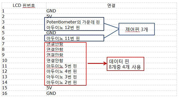
2. 스케치
#include <LiquidCrystal.h>LiquidCrystal이라는 라이브러리를 사용합니다.
void setup() {
  lcd.begin(16,2);                       //LCD 크기 지정, 2줄 16칸
  lcd.clear();                           //화면 초기화
  Serial.begin(9600);                    //시리얼 통신 초기화
}
LCD에 관한 설정을 setup함수에 먼저합니다.
lcd.begin함수는 lcd의 크기를 지정하는 함수입니다.
    lcd.print(lcdString);                //문자열 LCD에 출력
    Serial.println(lcdString);           //시리얼 모니터에 입력한 값 출력
    lcdString = "";                      //문자열 초기화
lcd.print(" "); //전 글씨 삭제lcdPrint함수를 통해 LCD로 출력합니다.
맨 밑에 빈줄을 출력하는 이유는 전에 쓴 글씨를 지우기 위해서 입니다.
빈 줄을 출력한 후 다시 커서를 재 위치로 지정하면
재입력시 화면에 새로 입력한 글자만 보이게 됩니다.
https://kocoafab.cc/tutorial/view/727
I2C LCD로 문자 출력하기
2017-11-01 10:45:08
[이전 학습가이드] 온습도 센서(모듈)로 온/습도 확인하기
개요
1) LCD란 무엇인가?
LCD는 Liquid Crystal Display의 약자로 액정표시장치를 말합니다. 여기에서 액정 (Liquid Crystal)이란 액체처럼 유체의 성질을 가지면서 고체처럼 광학적 성질을 가지는 물질입니다. 또한 액정은 고체표면에 액정이 특정 방향으로 정렬할 수도 있어, 전기적 신호를 가해 원하는 방향으로 배열하여 빛을 투과시키거나 차단시킬 수 있습니다.
LCD는 이러한 액정의 성질을 이용합니다. 빛을 내는 백라이트, 백라이트에서 나온 빛을 한 방향으로 투과시키기 위한 편광판, 각 픽셀에 대한 액정 배열을 조절하여 투과하는 빛의 양을 제어하는 TFT, 그 다음으로 액정이 순서대로 위치하여 구성이됩니다. 또한 컬러 지원여부에 따라 컬러 필터가 추가될 수 있습니다.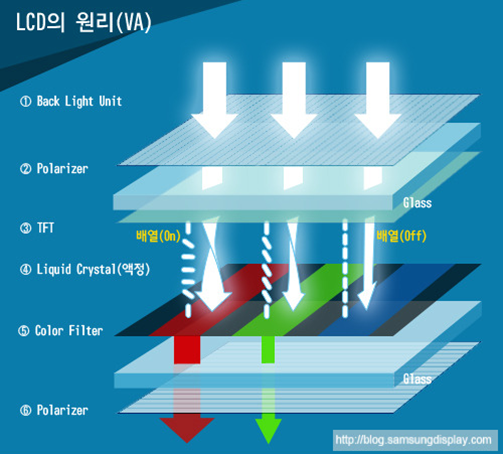
LCD는 얇고 가벼우며 소비전력이 적은 장점은 있지만, 시야각이 제한적이고 어두운 곳에서는 선명함이 떨어지는 단점이 있습니다. 현재 LCD는 손목시계부터 TV에 이르기까지 광범위하게 활용되고 있습니다.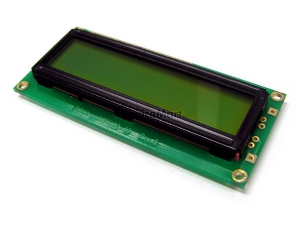
2) LCD 사용방법
이 예제에서 16개의 문자를 2줄로, 총 32개 문자를 표현할 수 있는 LCD를 사용합니다.
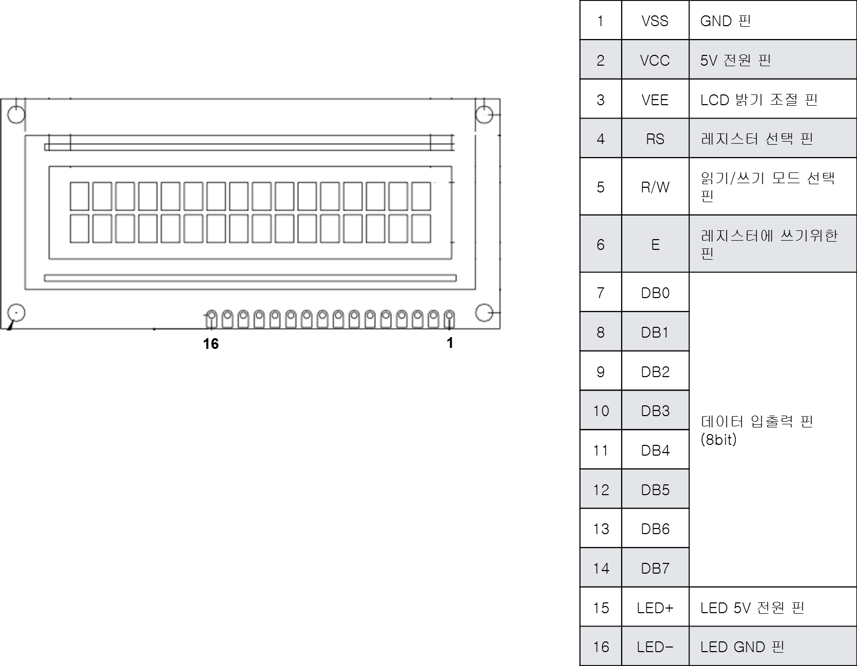
LCD는 아래와 같은 핀 배치로 구성되어 있으며, DB0-DB7까지의 핀들을 통해서 문자를 표시 할 수 있습니다.
3) I2C LCD란?
아두이노 프로젝트 제작에 있어 가장 보편적으로 사용되는 LCD는 16*2 Character LCD로서 1줄에 16개의 문자씩 총 2줄에 문자를 표기할 수 있는 LCD 입니다.
대부분의 16*2 LCD는 5V 전원을 통해 Backlight를 동작 시킬 수 있으며, 가변 저항을 통해 문자의 명암(선명도)를 조절할 수 있습니다.
기존 지니어스 키트 튜토리얼에서 16*2 LCD 사용법을 알아보실 수 있습니다.
< 16*2 Character LCD / 사진 출처 : oddwires >
위 그림과 같이 16*2 Character LCD를 사용하기 위해서는 총 12개의 배선이 필요하며, 문자의 선명도 제어를 위해 가변 저항을 추가적으로 연결해주어야 하기 때문에 사용하기 어렵습니다.
또한 아두이노와 연결하여 제어할 경우 총 6개의 digital Pin을 사용해야 하기 때문에 다양한 센서와 기타 부품을 사용할 경우에는 digital port 부족으로 사용에 한계가 있습니다.
이런 문제들을 개선하고자 개발된 모듈이 바로 I2C LCD 모듈입니다.
<I2C LCD 모듈 / 사진 출처 : addicore >
I2C LCD 모듈(I2C Converter)의 경우 기존의 16*2 Character LCD에 결합하여 사용할 수 있는 breakout board 형태의 모듈입니다.
모듈 단일 제품으로 판매하는 경우는 거의 없으며, LCD와 납땜되어 판매되는 경우가 대부분입니다.
I2C LCD 모듈(I2C Converter)를 사용하면 I2C interface를 사용해 LCD 제어가 가능해지며, 총 4개의 배선으로 아두이노에 연결이 가능합니다.
I2C interface를 사용하기 때문에 아두이노에 연결하여 제어할 경우 두 개의 AnalogPin(SDA, SCL)으로 제어가 가능합니다.
지니어스 키트에서 사용하는 I2C LCD(I2C Converter)의 사양은 아래와 같습니다.
- 1줄 16개 문자, 2줄 제어 가능.
- 동작 전압 : 5V
- i2C 주소(Address) : 0x20, 0x27, 0x3F
- 문자 선명도 : 가변 저항을 통해 문자의 선명도 조절 가능
- backlight : 점퍼 스위치를 통해 backlight On / Off
- 크기 : 41.5mm * 19mm * 15.3mm(L * W * H)
부품 목록
| NO | 부품명 | 수량 | 상세설명 |
| 1 | 오렌지 보드 | 1 | |
| 2 | I2C LCD | 1 | I2C 1602 Serial LCD Module |
| 3 | 점퍼케이블 | 4 | M/F(암수) 케이블 |
| 부품명 | 오렌지 보드 | LCD | 점퍼케이블 |
| 파트 | 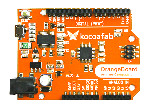 |  |  |
하드웨어 making
브레드 보드
1. I2C LCD의 GND핀을 오렌지보드의 GND핀에 연결합니다.
2. I2C LCD의 VCC핀을 오렌지보드의 5V핀에 연결합니다.
3. I2C LCD의 SDA핀을 오렌지보드의 아날로그 A4핀에 연결합니다.
4. I2C LCD의 SCL핀을 오렌지보드의 아날로그 A5핀에 연결합니다.
전자회로도
라이브러리 설치하기
1. '스케치 -> 라이브러리 포함하기 -> 라이브러리 관리' 를 실행합니다.
2. 'liquid crystal i2c' 로 검색 한 후 Frank de Brabander가 만든 LiquidCrystal I2C 라이브러리를 설치해 줍니다.
I2C LCD의 I2C 주소 확인하기
#include <Wire.h>

void setup()
{
  Wire.begin();

  Serial.begin(9600);
  while (!Serial);
  Serial.println("\nI2C Scanner");
}

void loop()
{
  byte error, address;
  int nDevices;
  Serial.println("Scanning...");
  nDevices = 0;
  for(address = 1; address < 127; address++ )
  {
    Wire.beginTransmission(address);
    error = Wire.endTransmission();

    if (error == 0)
    {
      Serial.print("I2C device found at address 0x");
      if (address<16)
        Serial.print("0");
      Serial.print(address,HEX);
      Serial.println("  !");
      nDevices++;
    }
    else if (error==4)
    {
      Serial.print("Unknow error at address 0x");
      if (address<16)
        Serial.print("0");
      Serial.println(address,HEX);
    }
  }

  if (nDevices == 0)
    Serial.println("No I2C devices found\n");
  else
    Serial.println("done\n");
  delay(5000);
}
I2C_LCD를 오렌지보드에 연결한 후 코드를 업로드 하면, 시리얼 모니터에 밑의 사진과 같이 현재 연결된 I2C_LCD의 I2C 주소가 나옵니다.
(* 밑의 사진은 주소 0x3F 로 나옵니다.)
소프트웨어 coding
/*
 제목		: I2C LCD에 문자 출력하기
 내용		: I2C LCD에 원하는 문자를 표시해 봅니다.
 */

// LCD를 쉽게 제어하기 위한 라이브러리를 추가합니다.
#include <LiquidCrystal_I2C.h>
#include <Wire.h>

// 0x3F I2C 주소를 가지고 있는 16x2 LCD객체를 생성합니다.(I2C 주소는 LCD에 맞게 수정해야 합니다.)
LiquidCrystal_I2C lcd(0x3F, 16, 2);

// 실행시 가장 먼저 호출되는 함수이며, 최초 1회만 실행됩니다.
// 변수를 선언하거나 초기화를 위한 코드를 포함합니다.
void setup() {
	// I2C LCD를 초기화 합니다..
	lcd.init();
	// I2C LCD의 백라이트를 켜줍니다.
	lcd.backlight();
}

// setup() 함수가 호출된 이후, loop() 함수가 호출되며,
// 블록 안의 코드를 무한히 반복 실행됩니다.
void loop() {
	// random 함수를 사용하여 0부터 2까지의 숫자중 랜덤하게 값을 받습니다.
	int value = random(0, 3);
	// 랜덤 값이 0이라면 아래의 조건을 실행합니다.
	if (value == 0) {
		// 0번째 줄 0번째 셀부터 입력하게 합니다.
		lcd.setCursor(0,0);		    		// 0번째 줄 0번째 셀부터 입력하게 합니다.
		lcd.print("  KocoaFab.cc  ");     	// 문구를 출력합니다.
	}
	// 랜덤 값이 1이라면 아래의 조건을 실행합니다.
	else if (value == 1) {
		lcd.setCursor(0,1);		    		// 1번째 줄 0번째 셀부터 입력하게 합니다.
		lcd.print("  Hello World!!  ");   	// 문구를 출력합니다.
	}
	// 랜덤 값이 2이라면 아래의 조건을 실행합니다.
	else if (value == 2) {
		// 0번째 줄 0번째 셀부터 입력하게 합니다.
		lcd.setCursor(0,0);
		// 아래의 문장을 출력합니다.
		lcd.print("  KocoaFab.cc  ");
		// 1번째 줄 0번째 셀부터 입력하게 합니다.
		lcd.setCursor(0,1);
		// 아래의 문장을 출력합니다.
		lcd.print("  Hello World!!  ");
	}
	// 1초간 대기합니다.
	delay(1000);
	// LCD의 모든 내용을 삭제합니다.
	lcd.clear();
}
* 코드 윗부분에 LiquidCrystal_I2C lcd(0x3F, 16, 2); 이 코드에서 0x3F를 위에서 찾은 자신의 I2C_LCD 주소로 바꿔 주셔야 LCD가 정상동작 합니다!!
코드에 I2C주소를 제대로 입력한 후에도 I2C_LCD에 글자가 출력되지 않으면 뒤에 가변저항을 돌려 LCD 문자 선명도를 조절해 보세요!
LCD를 활용한 프로젝트
LCD 게임기
LCD 화면에는 글자는 물론 각 종 원하는 그림, 혹은 문자를 자유롭게 출력할 수 있습니다.
위와 같은 특성을 이용해 LCD로 만든 게임 프로젝트입니다.
출처 : https://youtu.be/SjmdqRy22gc
https://kocoafab.cc/tutorial/view/689
I2C LCD 모듈
2016-11-10 16:51:54
개요
안녕하세요! 코코아팹입니다.
LCD는 화면에 문자를 출력해주는 용도적 특징 때문에 다양한 프로젝트에 사용되는 부품이라고 할 수 있습니다.
이번 튜토리얼에서는 LCD의 개념에 대해 알아보고, I2C 제어가 가능한 16*2 I2C Character LCD 모듈(I2C Converter) 사용법에 대해 알아보도록 하겠습니다.
<LCD를 활용한 프로젝트 : LCD를 활용해 알람 시계 만들기 >
LCD란?
LCD란 Liquid Crystal Display의 약자로 액정 표시 장치를 말합니다. 액정(Liquid Crystal)이란 액체처럼 유체의 성질을 가지며, 고체처럼 광학 성질을 가지는 물질을 말합니다.
또한 액정은 전기적 신호를 가해 원하는 방향으로 배열하여 빛을 투과시키거나 차단 시킬 수 있습니다.
< 사진 출처 : 삼성 디스플레이 블로그>
I2C LCD 모듈이란?
아두이노 프로젝트 제작에 있어 가장 보편적으로 사용되는 LCD는 16*2 Character LCD로서
1줄에 16개의 문자씩 총 2줄에 문자를 표기할 수 있는 LCD 입니다.
대부분의 16*2 LCD는 5V 전원을 통해 Backlight를 동작 시킬 수 있으며, 가변 저항을 통해 문자의 명암(선명도)를 조절할 수 있습니다.
코코아팹 튜토리얼을 통해 16*2 LCD 사용법을 알아보실 수 있습니다.
< 16*2 Character LCD / 사진 출처 : oddwires >
위 그림과 같이 16*2 Character LCD를 사용하기 위해서는 총 12개의 배선이 필요하며, 문자의 선명도 제어를 위해 가변 저항을 추가적으로 연결해주어야 하기 때문에 수고스러운 점이 있는 것은 사실입니다.
또한 아두이노와 연결하여 제어할 경우 총 6개의 digital Pin을 사용해야합니다. 몇 몇 안되는 센서 및 기타 부품과 함께 사용할 경우에는 큰 문제가 되지 않지만, 다양한 센서와 기타 부품을 사용할 경우에는 digital port 사용에 한계가 있습니다.
이런 사항들을 개선하고자 개발된 모듈이 바로 I2C LCD 모듈입니다.
<I2C LCD 모듈 / 사진 출처 :addicore >
I2C LCD 모듈(I2C Converter)의 경우 기존의 16*2 Character LCD에 결합하여 사용할 수 있는 breakout board 형태의 모듈입니다.
모듈 단일 제품으로 판매하는 경우는 거의 없으며, LCD와 납땜되어 판매되는 경우가 대부분입니다.
I2C LCD 모듈(I2C Converter)를 사용하면 I2C interface를 사용해 LCD 제어가 가능해지며, 총 4개의 배선으로 아두이노에 연결이 가능합니다.
I2C interface를 사용하기 때문에 아두이노에 연결하여 제어할 경우 두 개의 AnalogPin(SDA, SCL)으로 제어가 가능합니다.
제조사에 따라 제품 사양에 차이점이 있을 수 있으나 보편적으로 I2C LCD 모듈(I2C Converter)의 사양은 아래와 같습니다.
- 1줄 16개 문자, 2줄 제어 가능.
- 동작 전압 : 5V
- i2C 주소(Address) : 0x20, 0x27
- 문자 선명도 : 가변 저항을 통해 문자의 선명도 조절 가능
- backlight : 점퍼 스위치를 통해 backlight On / Off
부품 목록
실습을 위해서는 아래 부품이 필요합니다.
| NO | 부품명 | 수량 | 상세설명 |
| 1 | 오렌지보드 | 1 | Arduino UNO |
| 2 | 16*2 I2C Character LCD | 1 | |
| 3 | 점퍼케이블 | 4 | Female to Male |
| 부품명 | 오렌지보드 | 16*2 I2C Character LCD | 점퍼케이블 |
부품 사진 |
하드웨어 making
오렌지보드와 I2C 모듈의 연결 방법은 아래 표를 참고하세요.
| I2C 모듈(I2C Converter) | 오렌지보드 |
| GND | GND |
| VCC | 5V |
| SDA (Serial Data Line) | A4 / SDA |
| SCL (Serial Clock) | A5/ SCL |
브레드보드
전자 회로도(스키메틱)
소프트웨어 coding
I2C LCD 모듈(I2C Converter)을 제어하기 위해서는 라이브러리 추가해야합니다.
아래 링크를 통해 라이브러리를 다운로드 받을 수 있습니다.
- I2C LCD 모듈(I2C Converter) 라이브러리 다운로드 -
라이브러리 추가 방법은 코코아팹에 있는 튜토리얼을 참고하세요.
함수 설명
I2C LCD 모듈(I2C Converter)을 제어에 사용되는 함수 목록입니다.
* 선언된 객체 이름이 lcd일 경우를 가정한 내용입니다.
| lcd.begin(); | LCD를 사용을 시작 |
| lcd.display(); | LCD에 내용을 표시 |
| lcd.noDisplay(); | LCD에 내용을 숨김 |
| lcd.setCursor(col,row); | row, col의 좌표로 커서를 위치 |
| lcd.cursor(); | LCD에 커서를 표시 |
| lcd.noCursor(); | LCD에 커서를 숨김 |
| lcd.home(); | 커서의 위치를 0,0으로 이동 |
| lcd.blink(); | 커서를 깜빡임 |
| lcd.noBlink(); | 커서를 깜빡이지 않음 |
| lcd.backlight(); | LCD backlight을 킴 |
| lcd.noBacklight(); | LCD backlight를 끔 |
| lcd.write(val); | LCD 화면에 val 출력(아스키 코드 입력 시에는 아스키 코드에 해당하는 문자 출력) |
| lcd.print(val); | LCD 화면에 val 출력 |
| lcd.clear(); | LCD 화면의 모든 내용 지움 |
| lcd.scrollDisplayRight(); | 내용을 우측으로 1칸 이동 |
| lcd.scrollDisplayLeft(); | 내용을 좌측으로 1칸 이동 |
| lcd.autoscroll(); | 내용을 자동으로 우에서 좌로 스크롤 |
*Cursor 제어 함수와 관련하여 Cursor의 row와 col(줄과 행) 좌표에 대해 직관적으로 이해가 가지 않으시는 분은 아래 그림을 참고하시면 이해하기가 수월합니다!
< 16*2 LCD col & row 좌표 / 사진 출처 : Programming Electronics Academy >
LCD 제어에 필요한 함수를 알아보았으니 이제 직접 LCD에 문자를 출력해봐야겠죠?
LCD에 "Hello World"를 출력해봅시다.
아두이노 IDE의 [파일] - [예제] - [Arduino-LiquidCrystal-I2C-Library] - [HelloWorld]를 실행하시거나
아래 코드를 실행하시면 됩니다.
/*
제목 : I2C LCD 제어하기
내용 : I2C LCD Converter를 사용해 16*2 Character 제어해보기

이 소스코드는 kocoafab에서 작성하였습니다.
소스코드 배포시에는 출처를 남겨주시기 바랍니다.

E mail : contact@kocoa.or.kr
*/

#include <Wire.h>
#include <LiquidCrystal_I2C.h>

// Set the LCD address to 0x27 for a 16 chars and 2 line display
LiquidCrystal_I2C lcd(0x27, 16, 2);  // I2C LCD 객체 선언

void setup()
{
  // initialize the LCD
  lcd.begin(); // lcd를 사용을 시작합니다.
  lcd.backlight(); // backlight를 On 시킵니다.
  lcd.print("Hello, world!"); // 화면에 Hello, world!를 출력합니다.
}

void loop(){
}
이상 없이 소스가 업로드 되었다면 아래 사진과 같이 LCD 화면에 Hello, world!가 출력되는 것을 확인할 수 있습니다.
* 정상적으로 화면에 출력이 되지 않는다면, LCD와 오렌지보드 간의 연결을 다시 한 번 검토해주세요!
LCD와 오렌지보드와의 연결과 LCD 동작에 이상이 없는 것을 확인하였으니 시리얼 모니터를 통해 입력 받은 값을 바탕으로 LCD 함수들을 사용해 LCD를 제어해봅시다!
아래 소스 코드를 오렌지보드에 업로드시켜주세요!
시리얼 모니터로 입력받은 데이터에 따라 동작하는 내용은 아래와 같습니다.
- 1을 입력 받았을 때 : backlight가 1초가 소등되었다가 점등됩니다.
- 2를 입력 받았을 때 : LCD에 표시된 글자가 1초간 사라졌다가 나타납니다.
- 3을 입력 받았을 때 : Cursor가 1초간 깜빡이다가 사라집니다.
- 4를 입력 받았을 때 : 커서가 1초간 화면에 나타났다가 사라집니다.
- 5를 입력 받았을 때 : 화면에 표시된 내용이 1초간 우측으로 1칸 이동 후 원래 자리로 돌아옵니다.
- 6을 입력 받았을 때 : 커서가 화면에 표시된 후 커서 위치가 col 0부터 16까지 이동 후에 사라집니다.
/*
제목 : I2C LCD 제어하기
내용 : 시리얼 모니터를 통해 입력 받은 데이터로 LCD를 제어해보기

이 소스코드는 kocoafab에서 작성하였습니다.
소스코드 배포시에는 출처를 남겨주시기 바랍니다.

E mail : contact@kocoa.or.kr
*/

#include <Wire.h>
#include <LiquidCrystal_I2C.h>

LiquidCrystal_I2C lcd(0x27, 16, 2);  // I2C LCD 객체 선언

void setup()
{
  lcd.begin(); // lcd를 사용을 시작합니다.
  Serial.begin(9600);
  lcd.print("kocoafab.cc"); // lcd 화면에 kocoafab.cc 출력
  lcd.home(); // cursor의 위치를 0,0으로 이동
}

void loop() {


  if (Serial.available()) {  //시리얼 모니터를 통해 들어오는 데이터가 있다면
    char data = Serial.read(); // 데이터를 data 변수에 저장

// baklight 테스트
    if (data == '1') {
      lcd.noBacklight();
      delay(1000);
      lcd.backlight();
    }

// Display 테스트 (글자 표시)
    if (data == '2') {
      lcd.noDisplay();
      delay(1000);
      lcd.display();
    }

// Cursor Blink 테스트
    if (data == '3') {
      lcd.blink();
      delay(1000);
      lcd.noBlink();
    }

// Cursor 표시 테스트
    if (data == '4') {
      lcd.cursor();
      delay(1000);
      lcd.noCursor();
    }

// Scroll 테스트
    if (data  == '5') {
      lcd.scrollDisplayRight();
      delay(1000);
      lcd.scrollDisplayLeft();
    }

// Cursor 위치 변경 테스트
    if (data  == '6') {
      lcd.home();
      lcd.cursor();
      for (int i = 0; i < 16; i++) {
        lcd.setCursor(i, 0);
        delay(100);
      }
      lcd.noCursor();
      lcd.home();
    }
  }
}
많은 부품을 연결해야 하는 프로젝트 제작하고 있다면 I2C LCD를 사용해보는 것도 좋은 방법이겠죠?
이상으로 I2C LCD 사용 실습을 마쳐보았습니다!
https://develop-story.tistory.com/6
아두이노 16x2 LCD에서 한글 출력하기 1편입니다.
16x2 LCD 한글 출력 라이브러리는 제가 작년부터 개발하기 시작한 라이브러리인데요,
기존의 출력 방법(도트 방식)으로는 16x2 LCD에서 8글자 밖에 표시하지 못하며,
쀓뛣꿿과 같이 된소리나 자음군을 출력하지 못한다는 단점이 있었습니다.
저는 한글을 지워나가면서 출력한다면 여러 글자를 출력할 수 있겠다는 생각을 하게 되었는데요,
그렇게 해서 만들어진 것이 한글 출력 라이브러리 입니다!
그럼 본격적으로 한글 출력 라이브러리를 사용하는 방법을 알려드리도록 할게요:)
1. 한글 출력 라이브러리 다운로드
라이브러리를 다운로드 하는 방법은 두가지가 있는데요,
첫번째는 아래 링크에서 직접 zip 파일을 다운로드 한 후
아두이노 IDE에 들어가서
스케치>라이브러리 포함하기>.ZIP 라이브러리 추가..
에서 파일을 포함하는 것입니다.
https://github.com/junwha0511/LiquidCrystal_I2C_Hangul

junwha0511/LiquidCrystal_I2C_Hangul
2018학년도 백운 학술대회 최우수상. Contribute to junwha0511/LiquidCrystal_I2C_Hangul development by creating an account on GitHub.
github.com

두번째 방법은 아두이노 IDE 안에서 할 수 있는 방법인데요,
작년 11월에 라이브러리 매니저 등록이 승인 되어
한글 출력 라이브러리가 아두이노 라이브러리 매니저에 등록되어 있습니다.
아두이노 IDE에 들어가서
스케치>라이브러리 포함하기>라이브러리 관리
로 가시면 아래와 같은 창이 뜹니다.

검색창에 hangul을 검색해주시고
아래 사진과 같이 라이브러리가 나오면 설치해주세요:)

2. 한글 출력 라이브러리 사용법
이제 라이브러리를 설치했으니 사용법을 알아봐야겠죠?
한글 출력 라이브러리는 기존 Liquid Crystal_I2C 라이브러리를 확장한 것이니 때문에
기존 라이브러리의 함수를 모두 사용하실 수 있습니다.
(한글 출력 함수가 추가되었다고 보시면 됩니다.)
기존 라이브러리 사용법은 아래 링크를 참고해주세요!
https://kocoafab.cc/tutorial/view/727
I2C LCD로 문자 출력하기
[이전 학습가이드] 온습도 센서(모듈)로 온/습도 확인하기 개요 1) LCD란 무엇인가 ? LCD는 Liquid Crystal Display의 약자로 액정표시장치를 말합니다. 여기에서 액정 (Liquid Crystal)이란 액체처럼 유체의 성질을 가지면서 고체처럼 광학적 성질을 가지는 물질입니다. 또한 액정은 고체표면에 액정이 특정 방향으로 정렬할 수도 있어, 전기적 신호를 가해 원하는 방향으로 배열하여 빛을 투과시키거나 차단시킬 수 있습니다. LCD는 이러한 액정의 성질을 이용합니다. 빛을 내는 백라이트, 백라이트에서 나온 빛...
kocoafab.cc
아두이노 IDE에서 파일>예제>LiquidCrystal_I2C_Hangul의 printHangul 예제를 클릭하시면

아래와 같은 코드가 나옵니다.
#include<LiquidCrystal_I2C_Hangul.h> #include<Wire.h> LiquidCrystal_I2C_Hangul lcd(0x3F,16,2); void setup() { lcd.init(); lcd.backlight(); lcd.setDelayTime(1000); lcd.printHangul("dP wp vk dlf dlq sl ek",0); lcd.clear(); lcd.print("completed!"); } void loop() { // put your main code here, to run repeatedly: }
한글 출력과 관련된 함수는 두가지가 있는데요,
첫번째 함수는 lcd.printHangul(String txt) 입니다.
lcd.printHangul("")에서 ""안에 한글과 대응되는 영어를 입력하면 한글이 순차적으로 출력되게 됩니다
예를 들어 안녕하세요는 dks sud gk tp dy로 작성하시면 됩니다.
여기서 주의해야할 점은 띄어쓰기인데요, 한 글자씩 띄어쓰기를 해주셔야합니다.
공백을 출력하고 싶으신 경우 두번 띄어쓰기 하시면 됩니다.
두번째 함수는 lcd.setDelayTime(int time)인데요,
앞서 말씀드린 바와 같이 한글 출력 라이브러리는 한글을 앞 글자를 지워가면서 출력을 하는데,
이 함수로 출력되는 속도를 조절할 수 있습니다.
단위는 밀리세컨드(millisecond)입니다.
3. 출력 화면
아래 처럼 한글이 출력됩니다.
오늘의 포스팅은 여기까지입니다!:)
http://junwha0511.blog.me/221529144374





댓글
댓글 쓰기