Arduino PWM 2N2222
https://sizzf.tistory.com/19
2. 펄스(PWM)으로 부저 연주하기


회로를 보시면 새로운 부품이 보일겁니다. 아날로그회로에서 증폭기 역할을 해주는 npn트랜지스터입니다.
int speakerPin = 8;
int numTones = 10;
int tones[] = {261, 277, 294, 311, 330, 349, 370, 392, 415, 440};
// mid C C# D D# E F F# G G# A
void setup()
{
}
void loop()
{
for (int i = 0; i < numTones; i++)
{
tone(speakerPin, tones[i]);
delay(500);
}
noTone(speakerPin);
delay(1000);
}
새로운 함수가 보입니다. tone(pin,frequency)함수입니다.
tone(pin,frequency)는 pin번호에 frequncey값에 맞는 주파수를 출력하여 소리를 내게해주는 함수입니다. 이때 tone(pin,frequency,duration)으로 시간(ms)까지 설정이 가능 합니다. 또한 tone함수는 아두이노3번핀과 11번핀에서는 사용이 불가능 하며 31~65545의 주파수를 재생 가능합니다.
소리를 끄고 싶을때는 notone()함수를 사용하시면 됩니다.
소스코드 설명 : tones배열의 각각의 음계에 맞는 주파수를 저장한뒤 for문을 통해서 해당음계를 하나씩 소리냄
Simple Audio Player
https://www.arduino.cc/en/Tutorial/SimpleAudioPlayer
Hardware Required
Arduino Due Board
8-ohm speaker or headphones
Arduino shield with an SD card with cs CS 4 (like the Ethernet shield)
Componets to build an external audio amplifier
LM386 (low power audio amplifier)
10 kohm potentiometer
10 ohm resistor
2 x 10 µF capacitor
0.05 µF (or 0.1 µF) capacitor
250 µF capacitor
The Circuit
The shield sits on top of the Due with a micro-SD card in the slot. A .wav file named "test.wav" is in the card's root directory. For a simple test you can attach a pair of headphones directly to ground and DAC0, respecting the polarity.
To connect a speaker to the board you have add an amplification circuit connected between the DAC0 pin and the speaker. The amplification circuit will increase the volume of the speaker. There are many audio amplifiers available, one of the most common is the LM386. The following scheme shows how to build the circuit using the LM386 and a bunch of components. You can supply the LM386 connecting the Vs pin with different voltages sources, like for example the +5 V present on the 5V pin of the Arduino Due or an external 9V battery. The gain of the amplifier is given by the capacitor connected to pin 1 and 8 of the LM386. With the 10 µF capacitor the gain is set to 200, without the capacitor the gain is 50. With the potentiometer you can control the volume of the amplifier. Warning: do not connect the speaker directly to the pins of the Arduino Due.

LM386 electronic schematic

LM386 mounting on breadboard
Audio File
The Audio file to store on the SD card must be in the .wav format with 44100 Hz, 16-bit stereo quality.
Code
/*

  Simple Audio Player

 Demonstrates the use of the Audio library for the Arduino Due

 Hardware required :

 * Arduino shield with a SD card on CS4

 * A sound file named "test.wav" in the root directory of the SD card

 * An audio amplifier to connect to the DAC0 and ground

 * A speaker to connect to the audio amplifier

 Original by Massimo Banzi September 20, 2012

 Modified by Scott Fitzgerald October 19, 2012

 Modified by Arturo Guadalupi December 18, 2015

 This example code is in the public domain

 http://www.arduino.cc/en/Tutorial/SimpleAudioPlayer

*/

#include <SD.h>
#include <SPI.h>
#include <Audio.h>

void setup() {

  // debug output at 9600 baud

  Serial.begin(9600);

  // setup SD-card

  Serial.print("Initializing SD card...");

  if (!SD.begin(4)) {

    Serial.println(" failed!");

    while(true);

  }

  Serial.println(" done.");

  // hi-speed SPI transfers

  // 44100kHz stereo => 88200 sample rate

  // 100 mSec of prebuffering.

  Audio.begin(88200, 100);
}

void loop() {

  int count = 0;

  // open wave file from sdcard

  File myFile = SD.open("test.wav");

  if (!myFile) {

    // if the file didn't open, print an error and stop

    Serial.println("error opening test.wav");

    while (true);

  }

  const int S = 1024; // Number of samples to read in block

  short buffer[S];

  Serial.print("Playing");

  // until the file is not finished

  while (myFile.available()) {

    // read from the file into buffer

    myFile.read(buffer, sizeof(buffer));

    // Prepare samples

    int volume = 1024;

    Audio.prepare(buffer, S, volume);

    // Feed samples to audio

    Audio.write(buffer, S);

    // Every 100 block print a '.'

    count++;

    if (count == 100) {

      Serial.print(".");

      count = 0;

    }

  }

  myFile.close();

  Serial.println("End of file. Thank you for listening!");

  while (true) ;
}
See also
Audio library
https://www.circuitbasics.com/build-a-great-sounding-audio-amplifier-with-bass-boost-from-the-lm386/
BUILD A GREAT SOUNDING AUDIO AMPLIFIER (WITH BASS BOOST) FROM THE LM386
In this tutorial, I’ll show you how to build a great sounding audio amplifier with the LM386 Low Voltage Audio Power Amplifier. I built about a dozen different audio amplifier circuits with the LM386 but most of them had way too much noise, popping, and other interference. Finally I found one that sounds great, so I’m going to show you how to build it.

It’s not a “minimal components” audio amplifier. I added a bunch of extra capacitors to reduce the noise, and I added a bass boost control as well to make it sound even better. But before we start building, it might be helpful to get a little background information first…
LM386 BASICS
The LM386 is quite a versatile chip. Only a couple resistors and capacitors are needed to make a working audio amplifier. The chip has options for gain control and bass boost, and it can also be turned into an oscillator capable of outputting sine waves or square waves.
There are three varieties of the LM386, each with different output power ratings:
- LM386N-1: 0.325 Watts
- LM386N-3: 0.700 Watts
- LM386N-4: 1.00 Watts
The actual output power you get will depend on your supply voltage and speaker impedance. The datasheet has graphs that will tell you. I used a 9V battery for the power supply and it works great, but you can go down to 4V or up to 12V.
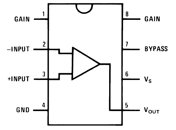
The pinout is shown in the diagram below:
Download the datasheet for more information about the output power, distortion characteristics, and minimum/maximum ratings:
The LM386 is a type of operational amplifier (Op-Amp). Operational amplifiers have a basic task. They take an input potential (voltage) and produce an output potential that’s tens, hundreds, or thousands of times the magnitude of the input potential. In an amplifier circuit, the LM386 takes an audio input signal and increases its potential anywhere from 20 to 200 times. That amplification is what’s known as the voltage gain.

GAIN VS VOLUME
After you build this amp and play with the volume and gain controls, you’ll notice that both appear to raise or lower the intensity of sound coming out of the speaker. So what’s the difference then? Gain is the amplification of the input potential and is a characteristic of the amplifier. Volume lets you adjust the sound level within the range of amplification set by the gain. Gain sets the range of possible volume levels. For example, if your gain is set to 20, the range of volume is 0 to 20. If your gain is set to 200, the range of volume is 0 to 200.
Gain control can be achieved by connecting a 10 μF capacitor between pins 1 and 8 . Without a capacitor between pins 1 and 8, the gain will be set to 20. With the 10 μF capacitor, the gain will be set to 200. The gain can be changed to any value between 20 and 200 by placing a resistor (or potentiometer) in series with the capacitor.
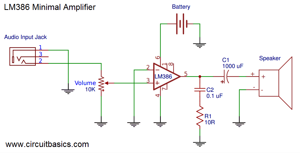
A MINIMAL LM386 AUDIO AMPLIFIER
Now that we have a little background information on the LM386, let’s start by building a bare bones LM386 amplifier with the minimum amount of components needed to make it work. That way you can compare it to the better sounding one we’ll build later on.
Here’s the schematic:

Here’s how to wire it if you’re using a breadboard:
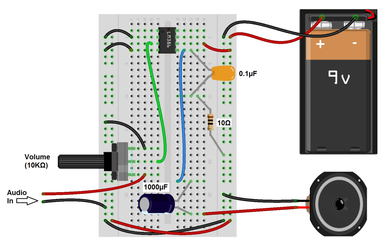
In the wiring diagram above, the audio input ground flows through the same path as the audio output ground. The output ground is “noisy” and will cause distortion in the input signal if it’s wired this way. The audio input ground is sensitive to any interference and any noise picked up will get amplified through the amplifier.
Make it a goal to keep the input ground separate from other ground paths as much as possible. For example, you can connect the grounds for the power supply, input, and output directly to the ground pin (pin 4) of the LM386 like this:
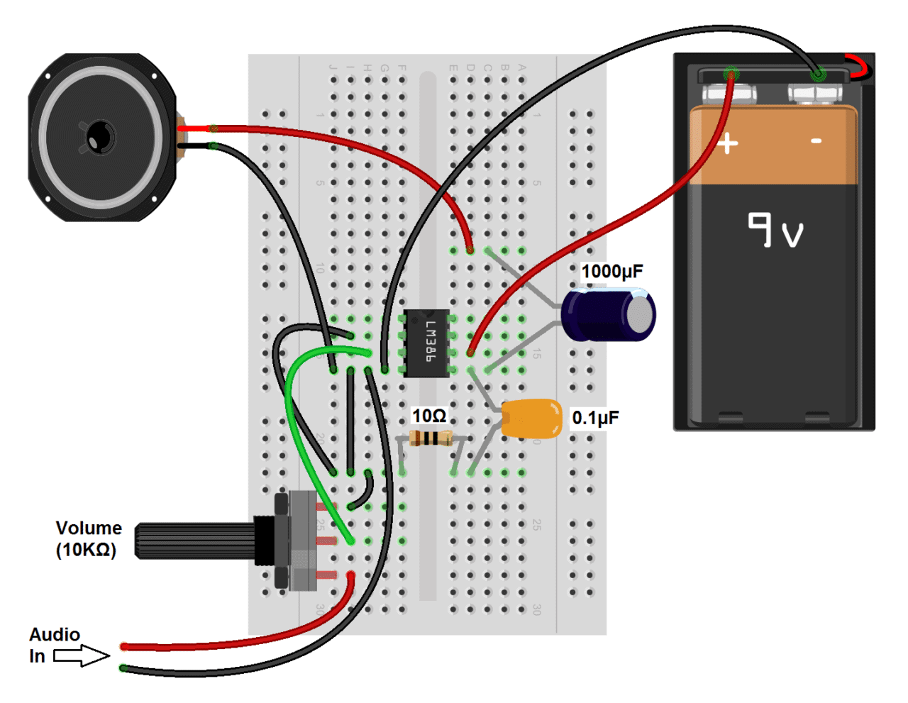
This will reduce the distance the input ground flows through the output ground. Connecting it like this should sound better than the first circuit, but you”ll probably still notice some noise, static and popping. We’ll fix that in the next circuit by adding decoupling capacitors and a couple RC filters.
A GREAT SOUNDING LM386 AUDIO AMPLIFIER
Now that you’ve seen the bare minimum of what it takes to make an audio amplifier with the LM386, lets build a higher fidelity version with an adjustable gain control.
Note: Most of the component values in this circuit aren’t critical. If you don’t have a particular value, try substituting something close and it will probably work.
Here’s the schematic:
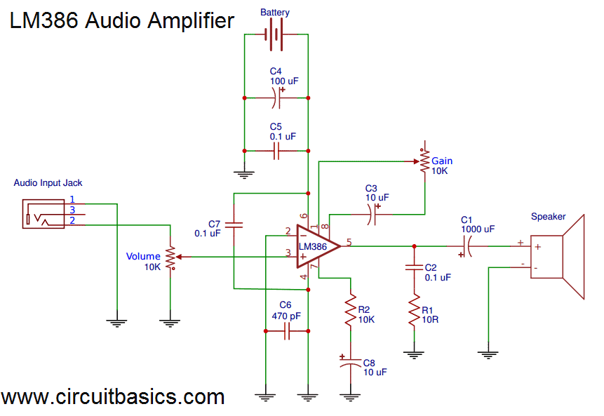

Several things in this circuit make it sound better:
- A 470 pF capacitor between the positive input signal and ground, which filters radio interference picked up by the audio input wires.
- 100 μF and 0.1 μF capacitors between the positive and negative power rails to decouple the power supply. The 100 μF capacitor will filter low frequency noise while the 0.1 μF capacitor will filter high frequency noise.
- A 0.1 μF capacitor between pins 4 and 6, for additional decoupling of the power supply to the chip.
- A 10K Ohm resistor and a 10 μF capacitor in series between pin 7 and ground to decouple the audio input signal.
This diagram will show you how to connect everything if you’re using a breadboard:
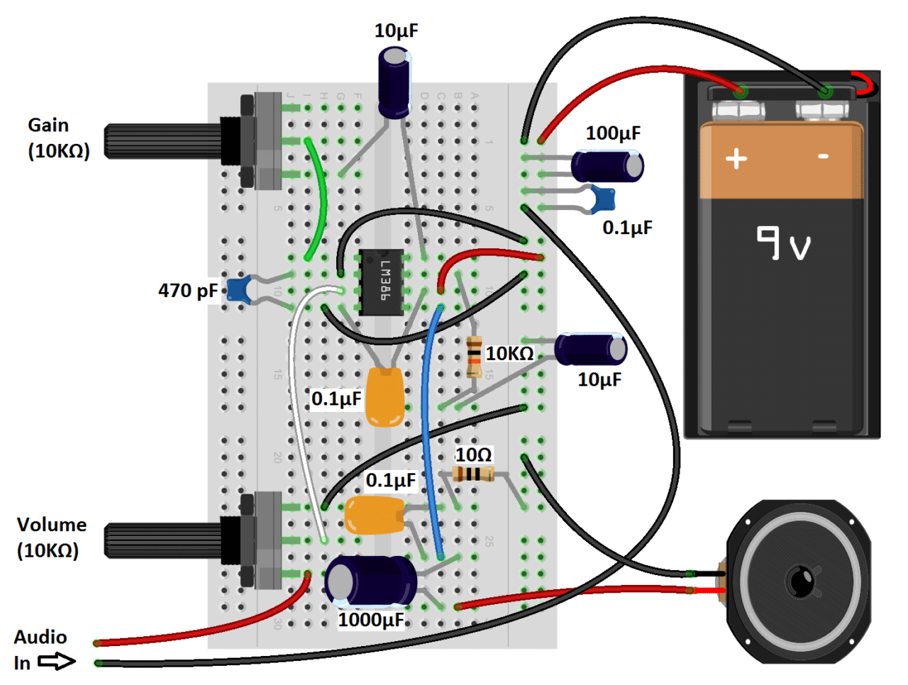
One thing to keep in mind when you’re wiring any audio amplifier is that the cleanest sound will result from keeping all wire connections and components as close to the chip as possible. Keeping the wires as short as possible will also help.
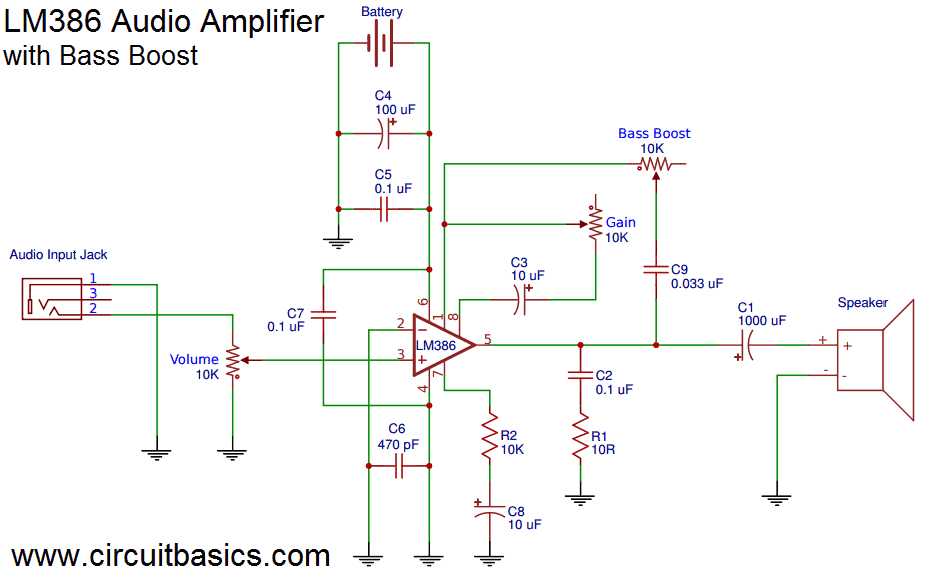
THE LM386 AUDIO AMPLIFIER WITH BASS BOOST
A cool feature of the LM386 is the option to add an adjustable bass boost to the amplifier. You’ll probably find that this is the best sounding circuit. The bass boost is basically just a low pass filter, and it removes most of the noise not taken out by the decoupling capacitors. All you need for the bass boost circuit is a 0.033 μF capacitor and a 10K Ohm potentiometer in series between pins 1 and 5:
Here’s the wiring diagram:
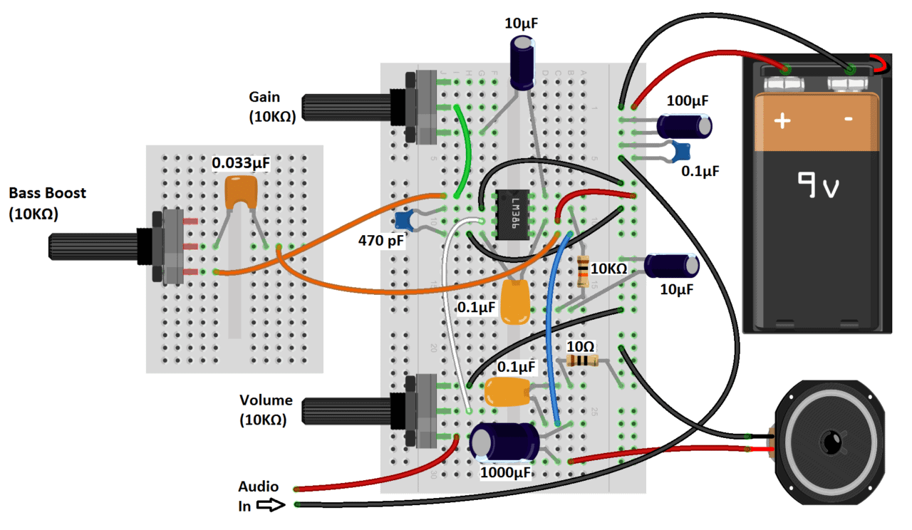
An easy way to connect the audio input in these circuits is by cutting the 3.5 mm audio jack from an old set of headphones and wiring it to breadboard pins. Check out this article, How to Hack a Headphone Jack to see how to do this with some common types of headphones.
Here’s the video version of this tutorial if you want to watch me build the amps and listen to them:
Thanks for reading! Hope you had fun experimenting with these amps as much as I did. If you’re ready to build some even better sounding and more powerful amps, we have tutorials on a few others:
- Hi-Fi 40 Watt stereo LM3886 amplifier
- 25 Watt stereo TDA2050 amplifier
- 12 Watt stereo and bridged mono TDA2003 amplifiers
The LM3886 is by far the best sounding amplifier, but it’s a fairly involved project. If you’re just starting to build audio amplifiers, I’d recommend working your way up to it by starting with the TDA2003, then moving up to the TDA2050.
Be sure to subscribe to keep updated on our posts as soon as they are published. And feel free to leave a comment if you have any questions or need help with anything in this article.


댓글
댓글 쓰기